CADS RC3D for Revit
The solution for reinforcement detailing and scheduling in Autodesk Revit
Introduction
CADS RC3D for Revit has been developed to make reinforcement detailing and scheduling within Revit® a practical and productive process.
CADS RC3D for Revit will make the transition from 2D detailing simpler and increase drawing productivity by providing enhanced functionality and an intuitive graphical interface.
Bar placement, annotation, labelling and schedule production for all concrete structures of any scale is now simpler and quicker with CADS RC3D!
Familiar Technology
A simple interface combined with powerful productivity tools, CADS RC3D has been developed by the team that brought you the industry standard for 2D detailing, CADS RC. That experience combined with a familiar interface has produced a practical solution with shallow learning curve. If you are not familiar with Revit but need to produce reinforcement details in Revit, this is the solution for you.
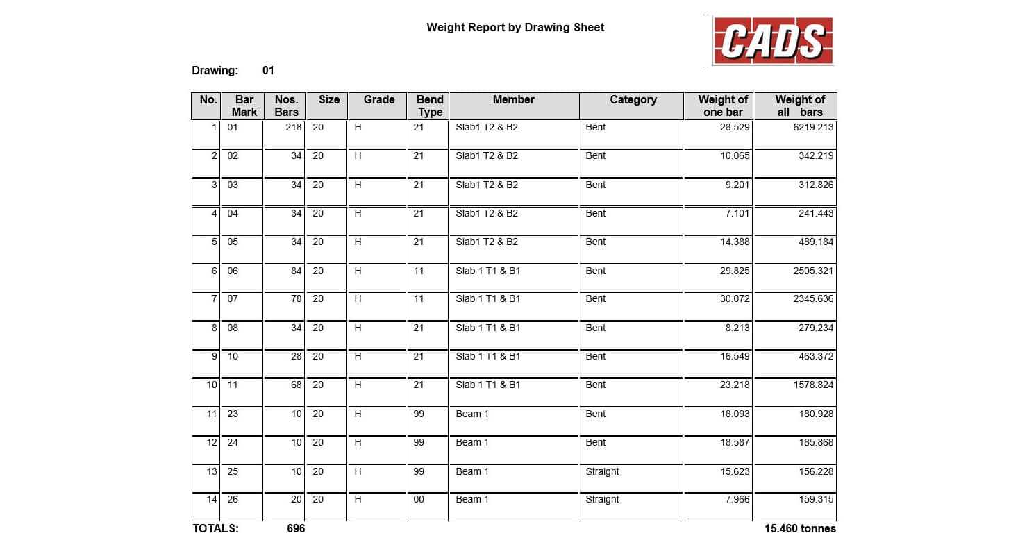
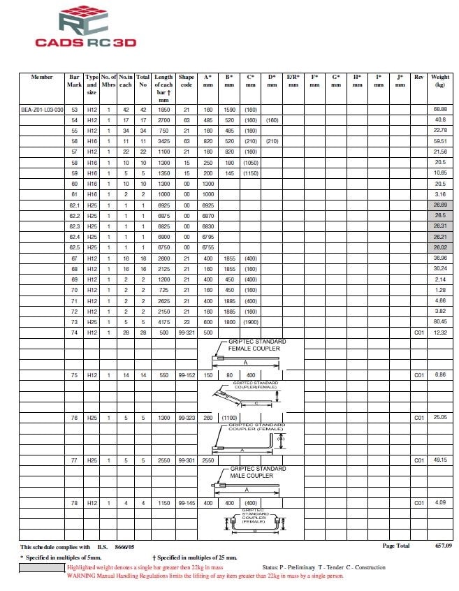
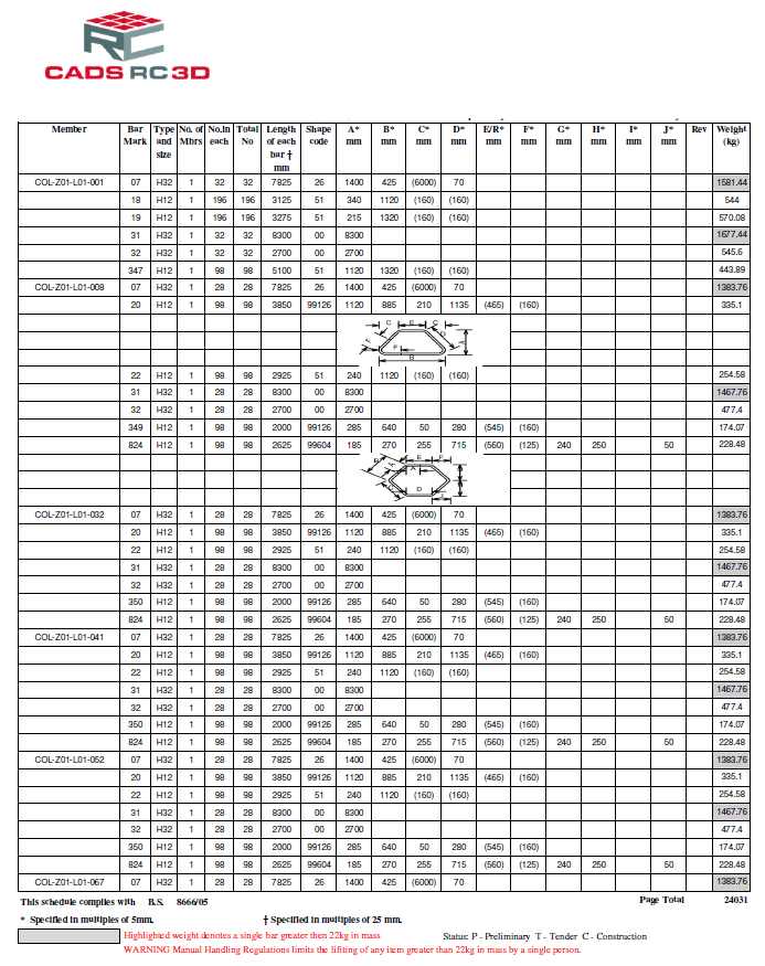
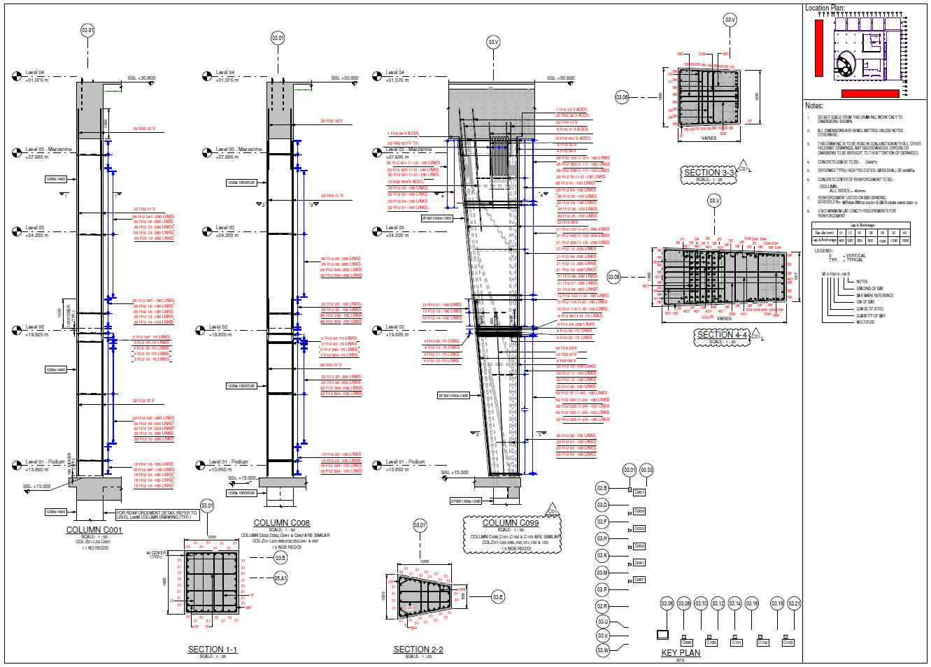
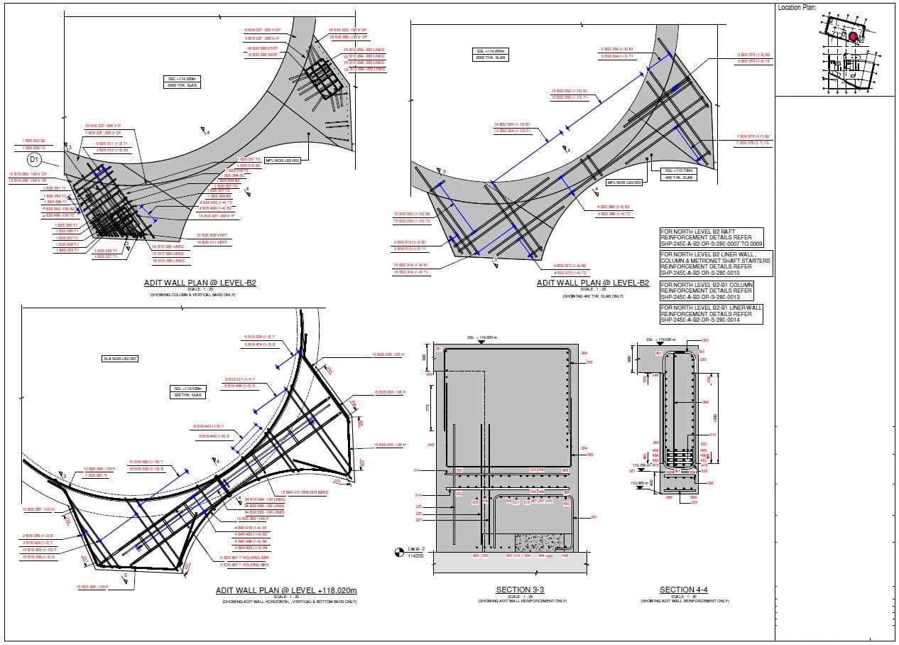
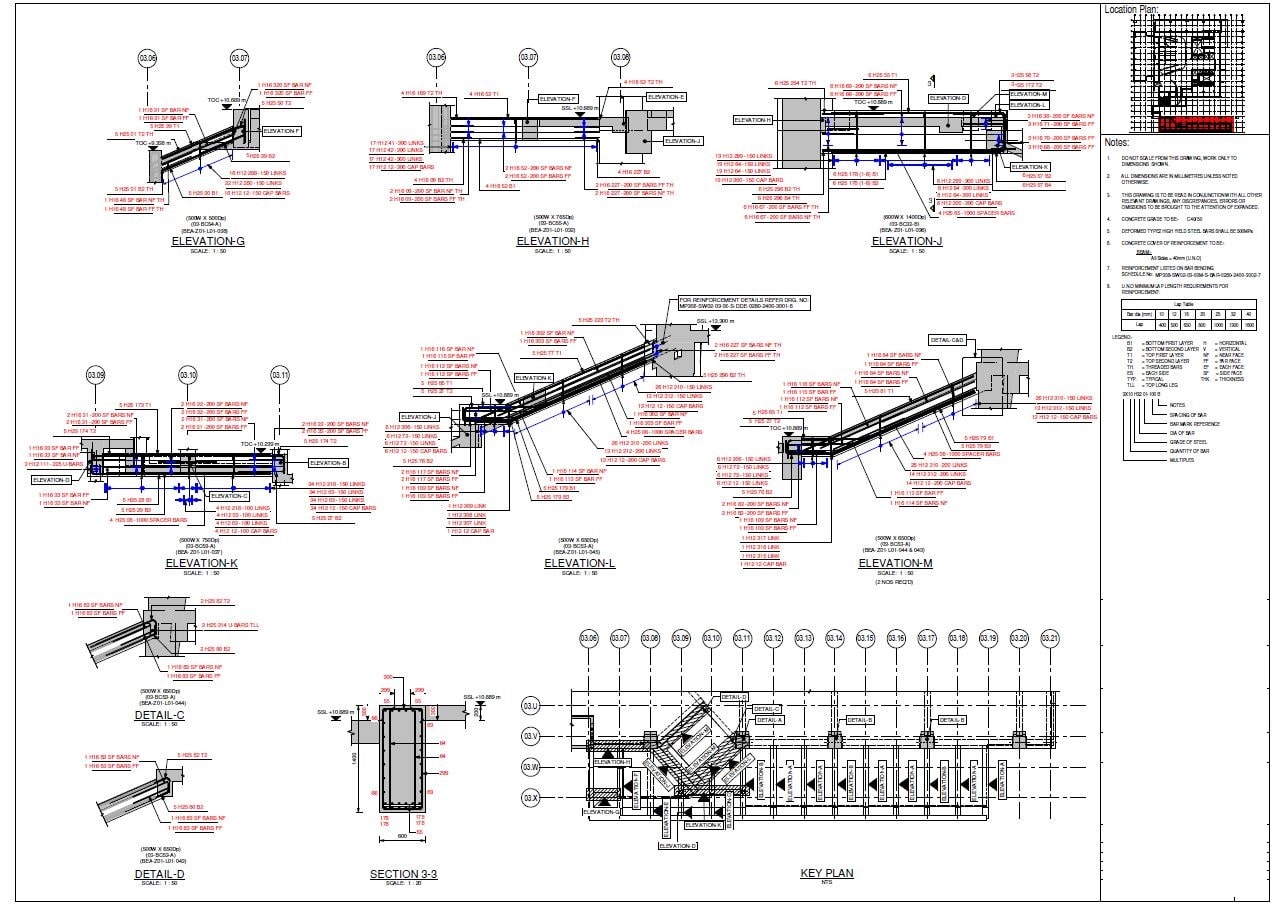
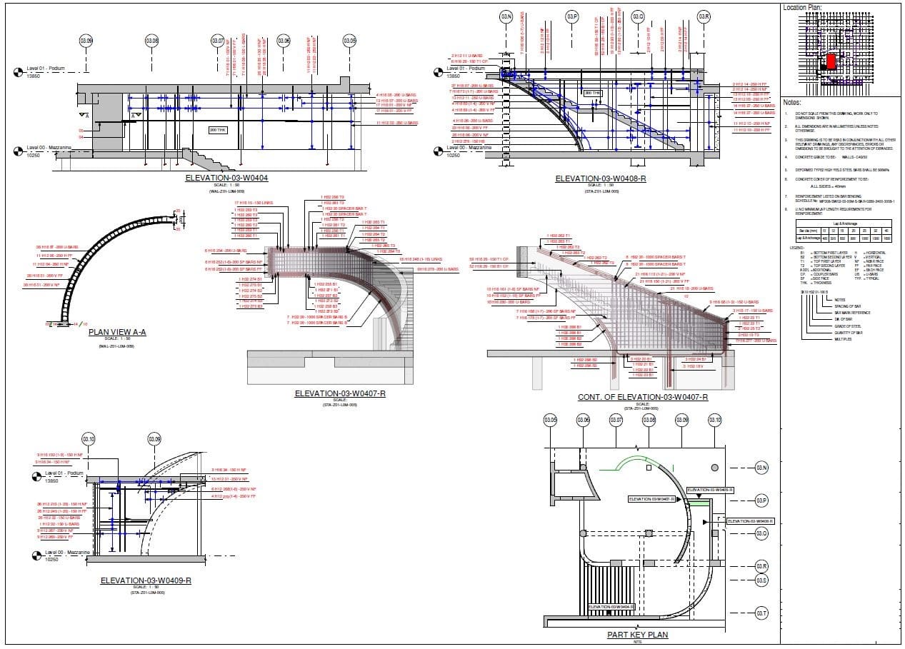
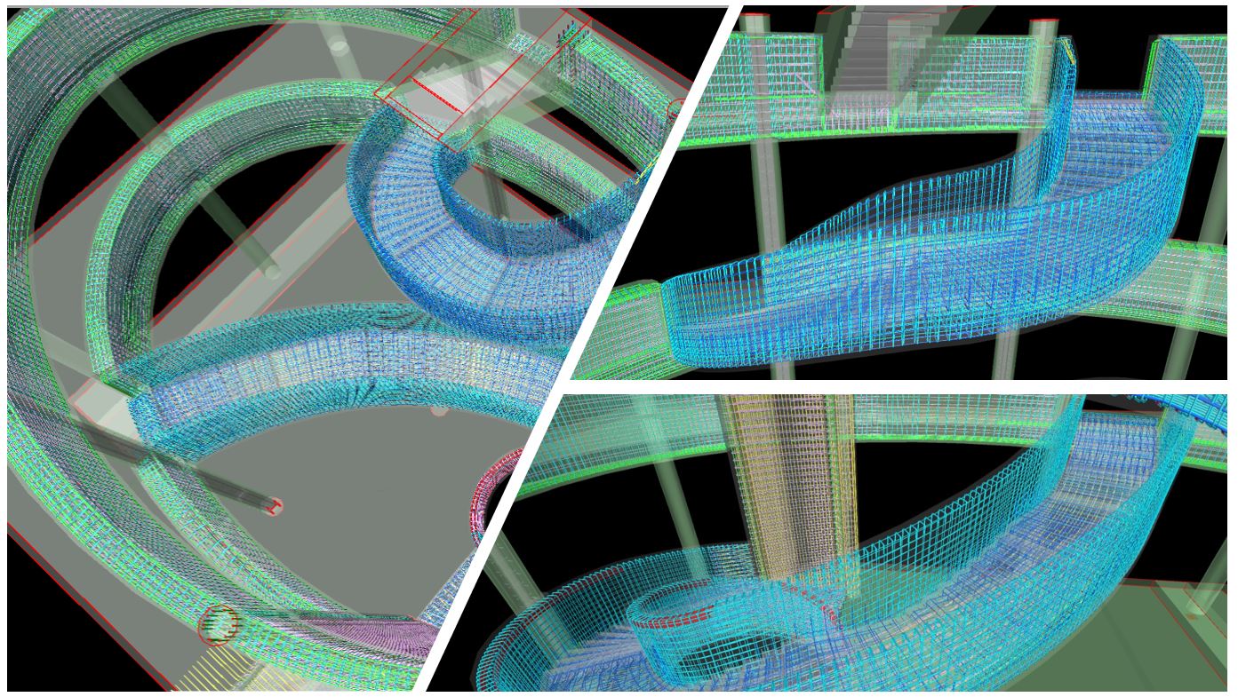
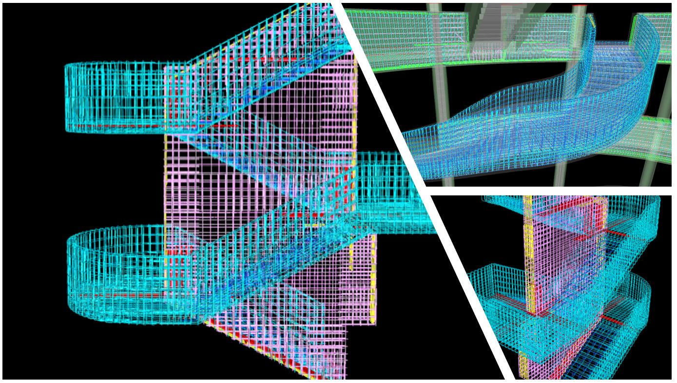
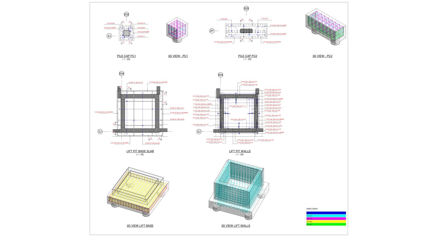
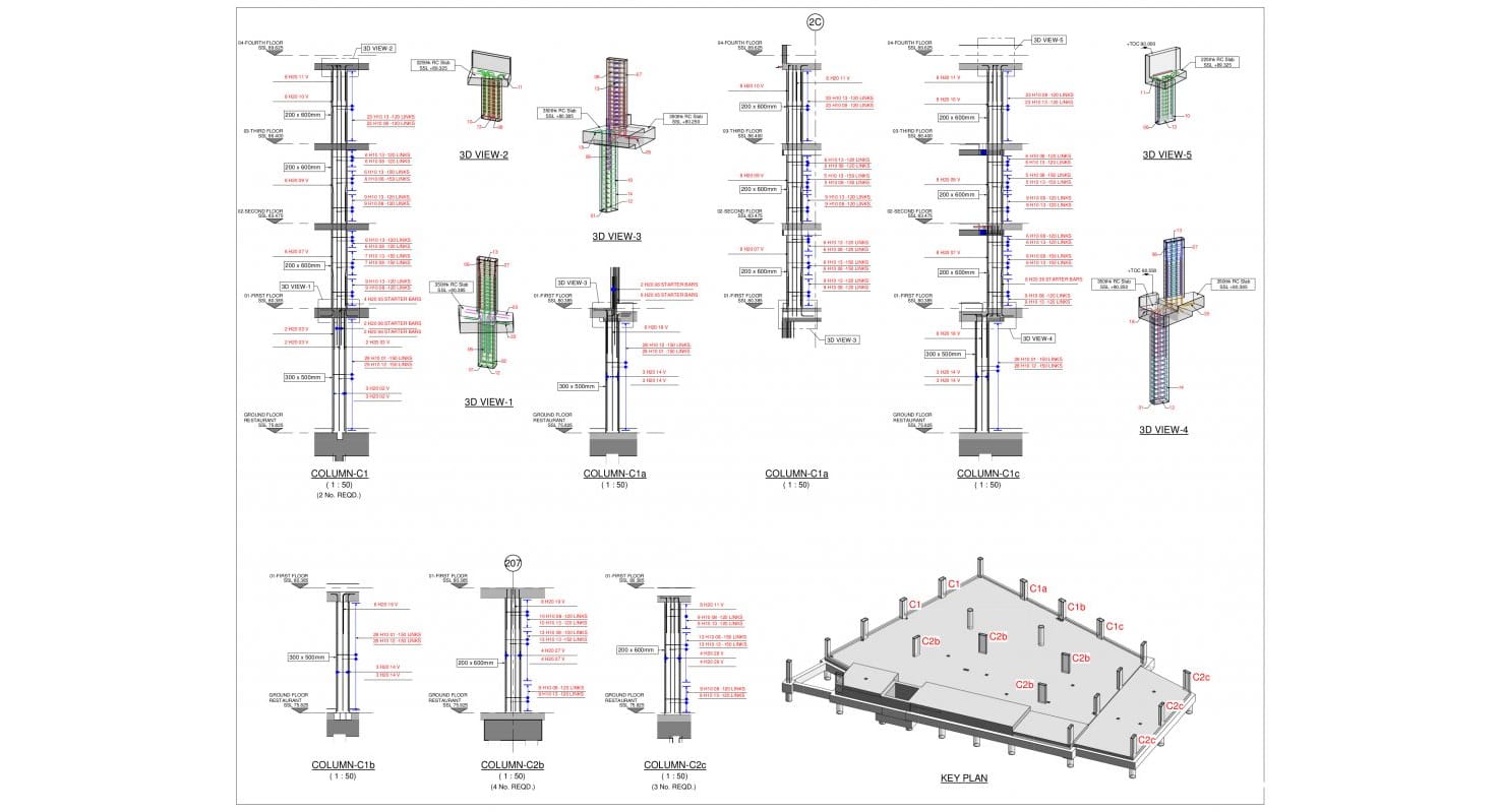
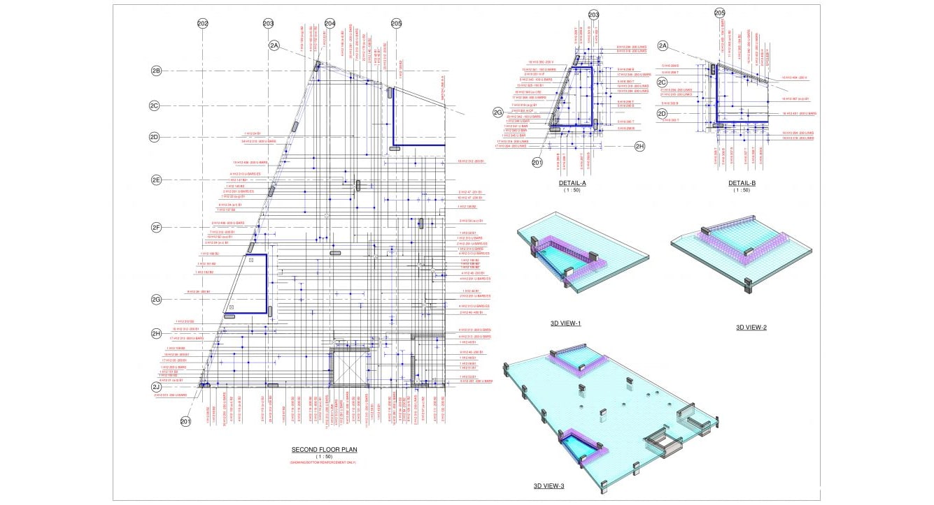
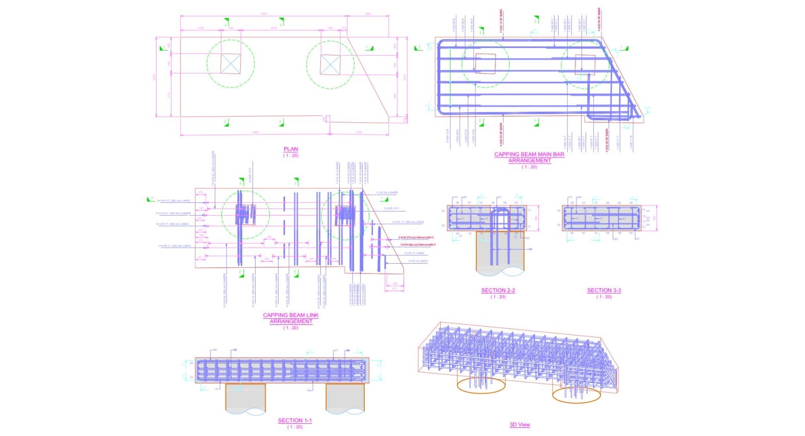
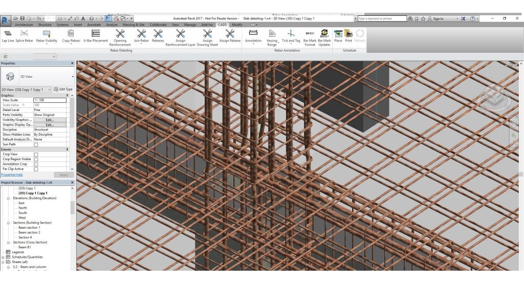
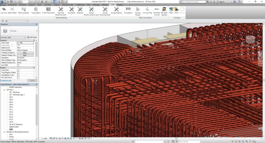
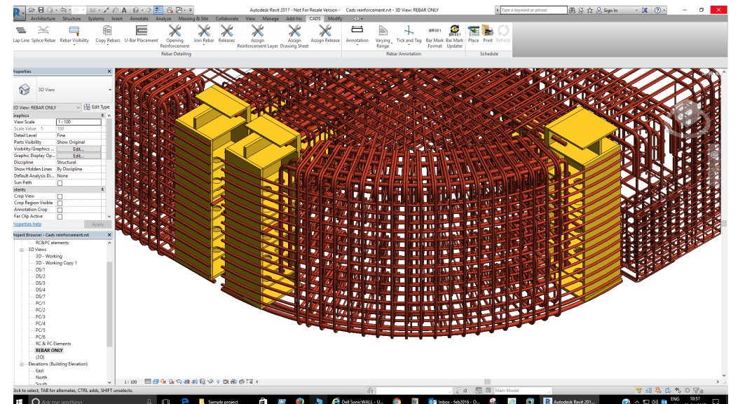
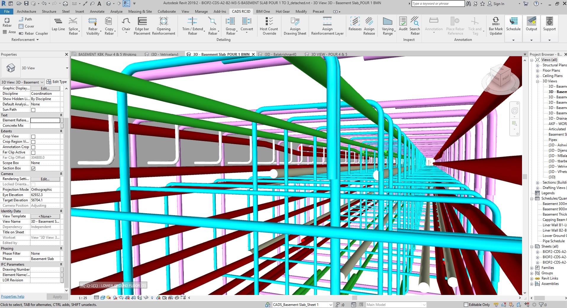
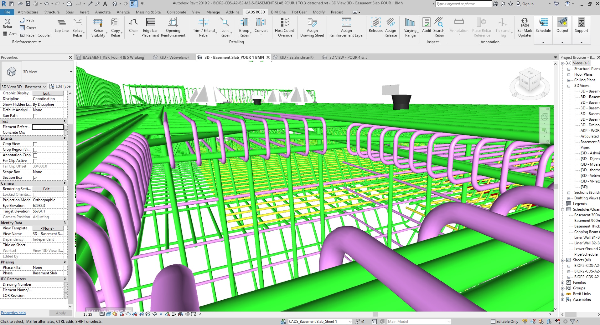
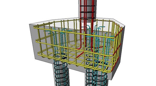
Screenshots of 3D Models, 2D Drawings, Schedules and Weight Reports
Features Included
- Customisable project settings automate the production of details to company standards
- Edit bar marks to suit your project, create your own bar mark logic, by host, drawing or project.
- Schedules and weight reports can be placed on drawing sheets, printed or exported to Excel using industry standard templates. The bar schedule and weights templates are easy to customise to company standards.
- Editing functions allow assemblies of reinforcement to be copied from one structure to another.
- “Host Count Override” to manually multiply the number of similar elements of a project in the schedule, i.e. detail one, schedule as many as you have on site!
- Groups edit to assign bars as staggered or alternate ranges thus adding full annotation and labelling.
- Split bars or groups of bars automatically by user defined lap line or specified stock lengths.
- Automatic ticks and tags and bar section labels, bar reference. Editing tools for ranges of bars, easily move range line or indicator bar.
- Layering of reinforcement by element type, a slab, a wall or foundation. Or assign reinforcement mats, T1, T2, B1, B2 etc. to different layers to aid visualisation and automate bar labelling with level detail.
- Reinforcement can be ‘joined’ together to form new bar shapes.
- Reinforcement bars can be trimmed and extended to the edge of openings or concrete surfaces.
- Openings in the structure can be identified and trimming reinforcement added.
- Path placement functions allow the rebar to be placed parallel to other rebar in the structure.
- Reinforcement can be assigned to a structure, release and drawing sheet.
- Electronically issue a drawing, the program adds revisions to sets of schedules to note changes and keep a list of historical schedule documents.
- Freeze and unfreeze reinforcement to control the content of schedules for issued drawings.
- Full support, telephone, online, by the experienced UK based CADS team, manual and free video tutorials also available.
Added Functionality
Bonus Programs
CADS RC3D for Revit comes with 2 additional programs to help with productivity.
CADS Markup
As part of a BIM process, import the design contour “heat maps” of required slab reinforcement from any suitable FEA program.
Then within Revit, using tools in CADS Markup, add the regions of intent using the required areas as reference.
Once completed, the intent areas will then be automatically converted to Revit native reinforcement ready for CADS RC3D to be used to complete the detail and schedules.
This then avoids the process of marking up reinforcement regions on hardcopy drawings and passing that to a detailer to convert manually to a computer.
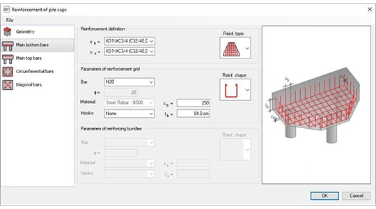
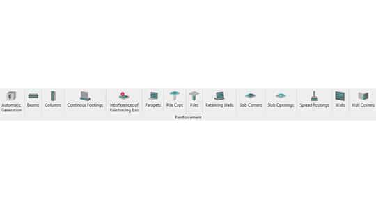
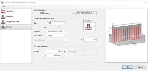
CADS Rebar Extensions
A library of menu driven detailing tools for many common structural elements such as beams, columns and pile caps. Also includes a reinforcement clash detection tool.
Simply fill in the details via a user friendly menu, this includes the geometry and reinforcement type and diameter, then click OK to complete the detail!

“We have been using the CADS suite of software for over 20 years, the quality of the software and the level of support has always been outstanding”
Jamie Seabrook, IT Manager
CADS RC3D for Revit 2025
Release date: 03/10/2024
CADS RC3D – v2025.0
RebarCAD 3D – v2025.0
CADS Rebar Extensions – v2025.1
CADS Markup Tool – v2025.1
CADS RC3D for Revit 2024
Release date: 14/11/2024
CADS RC3D – v2024.4
RebarCAD 3D – v2024.4
CADS Rebar Extensions – v2024.1
CADS Markup Tool – v2024.2
CADS RC3D for Revit 2023
Release date: 14/11/2024
CADS RC3D – v2023.7
RebarCAD 3D – v2023.7
CADS Rebar Extensions – v2023.4
CADS Markup Tool – v2023.4
Request a Free Trial for CADS RC3D
Request your free trial now to see how both experienced Revit users and professional RC detailers can quickly and easily model rebar in Revit with our extension.